
Part 1: Distance Modeling and Early Reflections
Part 2: Diffraction
Part 3: Beyond Early Reflections
Sound propagates as a wave and is subject to its behaviors. One of them is diffraction, which refers to “the bending of waves around the corners of an obstacle or through an aperture” [14]. “The amount of diffraction depends on the wavelength and the size of the obstacle. If the obstacle is small compared to the wavelength, the propagation seems to be unhindered by the obstacle. On the other hand, behind large obstacles no sound is observed. Consequently, low-frequency sound waves will spread over a larger angle around a corner than high-frequency waves. This is the reason why voices sound somewhat dull when heard from next room” [15].
.png)
Figure 1 - Waves bend around edges due to diffraction.
Before considering why and how sound designers can use diffraction from a practical standpoint, it is necessary to describe what it is in more detail.
Wave-Based and Ray-Based Methods for Simulating Sound Propagation
In his blog, our former colleague Benoit Alary explains diffraction, and describes the difference between ray-based and wave-based methods for simulating sound propagation [16]. In short, wave-based methods are more accurate in principle because they naturally simulate all the complex behaviors of waves. However, simulating sound propagation using wave-based methods often requires that the pressure is known at any given position and time, which is very expensive both in CPU and memory. In contrast, ray-based models of sound propagation use rays to represent a single point on a wavefront that will eventually reach the listener, and is therefore a much simpler calculation. While classic ray-based models model reflections by casting rays and making them reflect on surfaces, they typically neglect the wave properties of sounds, like diffraction [17].
It is instructive to examine simulations of wave-based models to see where classic ray-based models fall short. For example, let us observe one frame of Brian Hamilton’s animation of sound propagation generated from a wave-based simulation in Benoit’s blog [18]. In this frozen simulation, a perturbation has happened at the location of the orange X, and the ensuing wavefront has propagated outwards until the left side has hit a wall, reflected, and traveled beyond the corner. At this point we see a dim circular wavefront emerging from the corner. This is the result of diffraction.
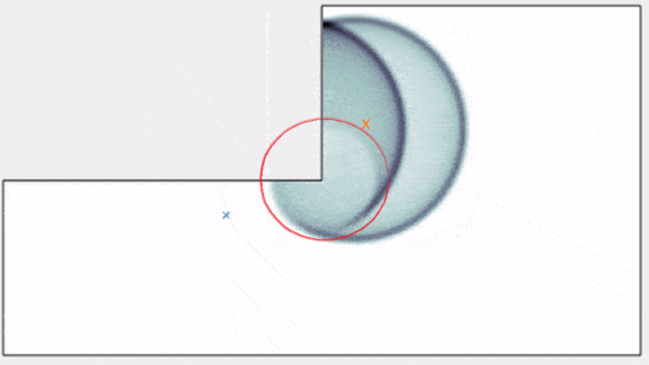
Figure 2 - Still image in the wave simulation animation of [18 ]. The emitter has been marked as an orange X, the outer rim corresponds to the wavefront of the “direct sound”, the half rim inside corresponds to the reflection from the wall, and the dim perturbation marked by the red circle corresponds to diffraction at the corner.
Ray-Based Diffraction
Although it is not simulated in the example above, it is possible to bolt an explicit model of diffraction on top of classic ray-based methods. There are several classes of these models. For those interested, Savioja et al’s overview referenced above surveys them quite extensively. With video games in mind, Tsingos proposed in 2001 a ray-based model of sound propagation using the Uniform Theory of Diffraction (UTD) [19]. The UTD models diffraction of light and electromagnetic waves, and predicts the amplitude and phase of a ray after it hits an edge. It takes into account the wedge shape, incident ray angle and frequency, among other things. Of course, as with all models, it relies on several assumptions. For example, the edge should be infinitely long. Since in practice, it never is, the model will simply be less accurate when the edge is short.
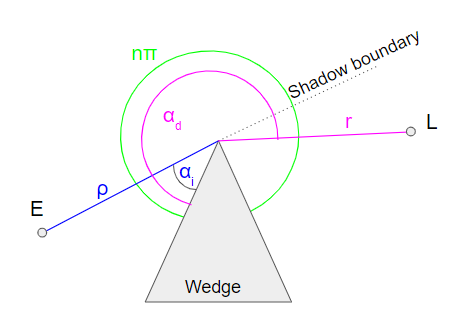
Figure 3 - Parameters of UTD as presented by [19] Tsingos: A source E diffracts on the tip of a wedge, and the UTD predicts its magnitude and phase at the listener position L. It depends on incident distance and angle ρ and αi, diffracted distance and angle r and αd, and wedge shape nπ.
The UTD defines three zones for given wedge and emitter positions: the shadow, view and reflection zones. Here they are illustrated on top of the frozen animation used above, where the orange X marks the location of the source.
.png)
Figure 4 - Diffraction zones. The orange X marks the location of the source. The shadow zone is defined where there is no line of sight between the emitter and listener, the reflection zone is where there are both line of sight and specular reflections due to the surface adjacent to the wedge, and the view zone is where there is only line of sight. The yellow circle highlights the diffraction in the view zone.
Practical Use Cases with Diffraction
Hearing Sounds Behind Obstacles - Shadow Zone Diffraction of the Direct Path
Now, why should we bother spending precious CPU cycles to compute diffraction rays? The first and most obvious need is to solve the shadow zone diffraction of the direct path. In classic ray-based methods, there is no sound in the shadow zone. Tsingos says that “diffraction is important for correct interpretation of acoustic environments, especially when the direct path between sound source and receiver is occluded” [19]. In real life, we hear things that are behind a corner thanks to diffraction, and compared with silence, its effect is extremely significant. Games tackle this problem with varying degrees of sophistication, usually by using statistical approaches based on ray casting and driving an obstruction factor accordingly.
Rolling Off Early Reflections - View Zone Diffraction
Diffraction in the view zone is much more subtle than that in the shadow zone because there is already a line of sight between the emitter and the listener. The wavefront coming directly from the emitter is much louder than the one due to the diffraction on the edge. For this reason, some acoustics engines using ray-based methods don’t even bother modeling it.
Modeling it has a practical use, however. Consider figure 4 again. In the view zone, without diffraction, the listener is only hit by the direct sound. However, as highlighted by the yellow circle, you can plainly see that the reflected wavefront extends into the view zone due to diffraction. Indeed the transition between the zone of specular reflection and absence of reflection is not infinitely sharp, and view zone diffraction can be used as a way to smoothly roll off between zones. From a ray’s perspective, view zone diffraction can be represented by a “diffracted reflection ray”, as shown in figure 5.
.png)
Figure 5 - Ray-based representation of view zone diffraction: the reflection ray of the surface adjacent to W “diffracts” into the view zone from the reflection-view boundary. The angle α can be used as a control to smoothly transition between the reflection and view zones.
Reflection zone diffraction
Diffraction also occurs in the reflection zone, but since it is in competition with both the direct sound and specular reflections, it is even less significant than view zone diffraction. It certainly causes some interference patterns, which may or may not, add to the realism of the rendering.
Modeling all these phenomena does not come for free, and as we can see, there are diminishing returns in modeling all of them. In parallel, in the light of our findings regarding the subjectivity of distance attenuation discussed in Part 1 of this blog series, an important, open question is how much accuracy is needed in the model?
Diffraction in Wwise
We have seen that even a phenomenon as straightforward as distance attenuation often needs to be “reinterpreted” by designers using various curves that map to volumes and filters, to achieve their desired aesthetics and plausibly fit sounds with the visuals. We decided to use the same creator-empowering logic for diffraction. Our goal is to provide tools to sound designers so that they can work with obstructing or finite geometry, and let them define how sounds roll off around edges. To this end, we chose to have Wwise Spatial Audio drive an abstract “diffraction coefficient”, instead of wasting CPU by computing the complex formulas of the UTD (which already are just an approximation).
Presently, this coefficient is computed directly from the angle of the ray with the shadow zone boundary, for shadow zone diffraction. This means that factors such as incident angle, wedge shape and edge length are neglected.
.png)
Figure 6 - Diffraction coefficient in Wwise. The angle of shadow zone diffraction (of the direct path) is taken from the shadow boundary, while the angle of view zone diffraction (that is, diffraction of reflections) is taken from the reflection boundary.
Example: Shadow Zone Diffraction of the Direct Path using Obstruction
You may use Wwise Spatial Audio to replace your game-driven obstruction system, and let it compute diffraction paths around edges of the geometry that it is made aware of. To do this, tick the “Enable Diffraction” checkbox for the desired sounds. The computed diffraction coefficients may be used to drive obstruction, or a special Diffraction built-in game parameter, which you can then map to volume and filtering to your liking.
.png) (a)
(a)
.png)
(b)
.png)
(c)
.png)
(d)
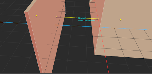
Figure 7 - Setting up shadow zone diffraction of the direct path in Wwise. (a) Enabled Diffraction in the Positioning tab. (b) Diffraction drives project-wide Obstruction curves, if desired (default initialization setting). (c) 3D Viewer: Two diffraction edges, with ~34% and 17% respectively (not visible). The total diffraction coefficient is the sum of the cascaded edges’ diffraction (~51.8%). The yellow emitter corresponds to the real emitter position as set by the game, and thus relates to the transmission of the sound through the obstacle. The purple emitter represents the origin of the incident diffraction ray. (d) The Voice Inspector, depicting Bus Volume and LPF driven by Obstruction, itself driven by Diffraction.
Example: View Zone Diffraction at the end of an Alley
Picture an alley surrounded by walls. As soon as the listener exits the alley, there are no more specular reflection paths from sounds that it emits. This can lead to a drastic drop in reverberant energy, that will be even more perceivable than in reality if only first order reflections are simulated, since we tend to exaggerate the volume of early reflections when they are scarce, as we have seen in Part 1 of this blog series. As explained above, view zone diffraction can help you fill up these dead zones and transition smoothly between areas of higher and lower reflection density: in Reflect, edit the diffraction-driven volume and filter curves.
(a)
.png)
(b)
.png)
(c)
.png)
(d)
Figure 8 - (a) Emitting listener in the middle of an alley, in the 3D Viewer. (b) Image sources in Reflect. (c) Emitting listener at the end of the alley: diffracted reflection on the right wall reaches the listener with 24.5% diffraction. (d) Image sources in Reflect, overlaid on top of the diffraction-dependent curves: the diffracted reflections undergo additional low-pass filtering.
Diffraction Versus Other Phenomena
Higher Reflection Orders
Independently from diffraction, enabling higher reflections orders may also help fill up dead zones. Second and higher order reflections may reach the listener where the first reflections could not. You should experiment to see which method works best for you, both in terms of quality and CPU cost.
.png)
.png)
.png)
Figure 9 - Higher order reflections may help mitigate the abruptness of the transition between inside and outside the alley, in addition to, or in place of diffraction. See how the number of visible rays gradually decreases as the listener moves away from the alley.
Scattering
In reality, the listener located at the end of the alley in the example above would also be hit by reflections because the surface of the wall is likely not infinitely smooth, so the reflected wave is not entirely specular. In ray-based methods, this is modeled by scattering, which is a property of the material and correlates with its roughness. It defines the ratio of energy generating diffuse reflections compared to the specular reflection (see figure 10). The rougher it is, the more energy will be reflected as diffuse reflections. Since Wwise Spatial Audio does not model scattering at the moment, designers will typically exaggerate the contribution of diffraction.
.png)
Figure 10 - Scattering: Defines how much an incident ray results in multiple diffuse reflections (in random directions) versus one specular reflection.
Effect of Geometry
We have just seen how various acoustic models may be used or abused in order to mitigate problems such as abrupt transitions or dead zones, or compensate for the phenomena that are not modeled. But all the flexibility you get with freely mapping acoustic parameters like diffraction to volume and filtering has a limit. Take the example of a curved convex surface. In computers they are always approximated with piecewise flat surfaces. So there will be dead zones without specular reflection. You can fill these gaps with diffraction. However for a given curved surface, you will get somewhat different results depending on how many triangles it is made up of.
Here is another example. Imagine that you stand in front of a wall that has a bookcase mounted on it, or paintings and other decorations. All the tiny edges should produce diffraction rays. Now imagine that these details are shrunk to the point that it just appears like the surface’s material is not perfectly smooth. As we have seen before, this is typically modeled with scattering: Statistically, you would be receiving a plurality of (diffuse) rays because of the relative orientation of microscopic parts of the wall. Intuitively, scattering can probably be viewed as a macroscopic view of diffraction occurring at a microscopic level.
However it is unlikely that modeling of diffraction at a microscopic level will ever converge to a satisfying scattering effect, at least in Wwise, for two reasons:
1. Even the highest level of details of game geometry will never be faithful to all the little imperfections of real life which make it sound real.
2. The diffraction model is greatly simplified and its effects are freely interpreted.
Instead, we recommend that you keep the sound propagation geometry consistent throughout your game in terms of level of details, and make it be reasonably simple. If you find your specular reflections sounding unnatural and want to blur them a little, you might get better results at a lower cost if you adopt a DSP approach instead. Try adding a filter in series with Wwise Reflect for example, and come up with your own secret sauce!
Stick around for the next and last blog of this series, where we will discuss late reverberation and future developments of Wwise Spatial Audio.

Comments